AT THE MACHINE
Machinery Pod
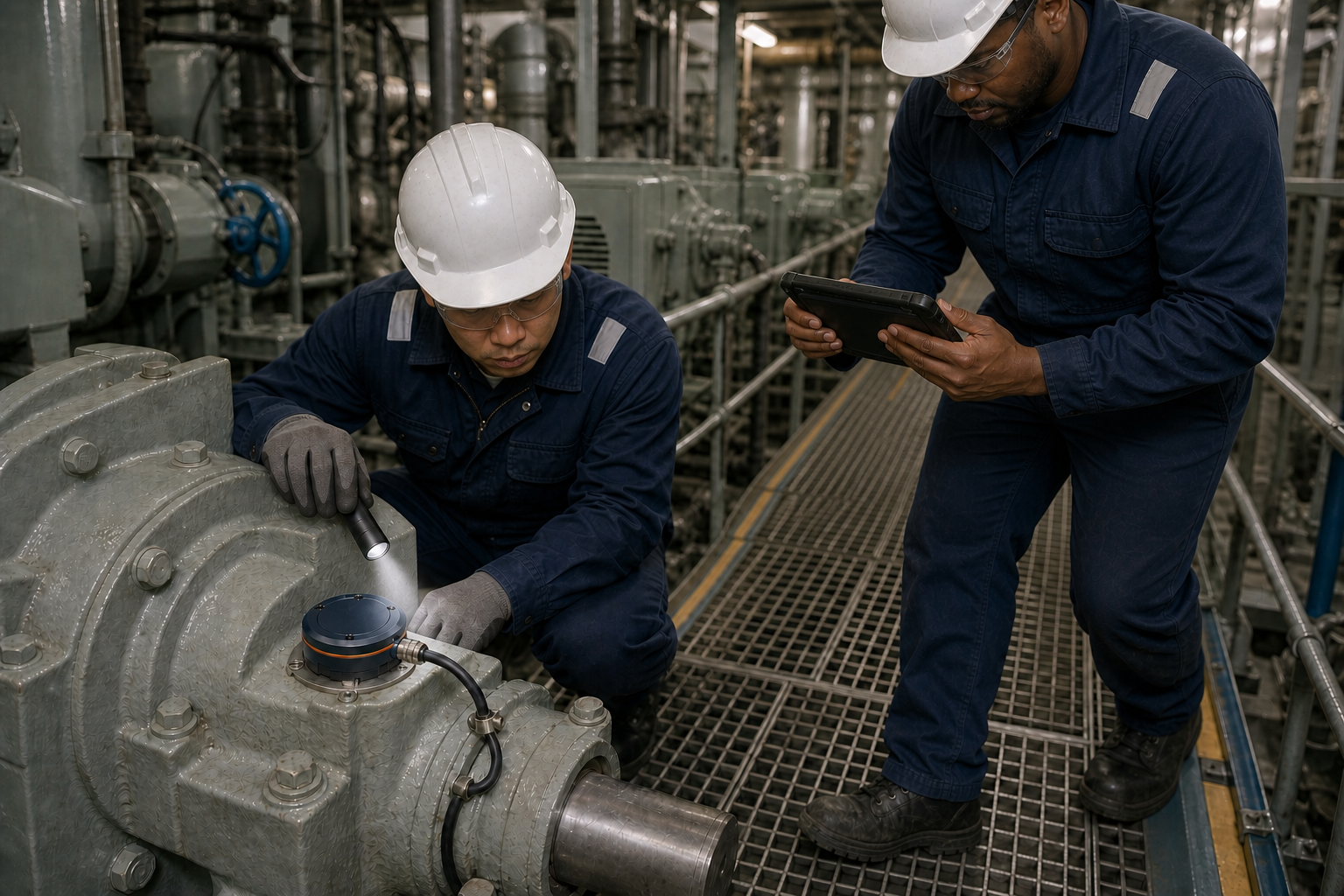
Fixed, wired sensing at a selected stationary bearing housing, with a protected cable path and a mounting interface designed for secure, serviceable installation.
CHIEF ONE MACHINERY HEALTH · DEVELOPMENT PREVIEW
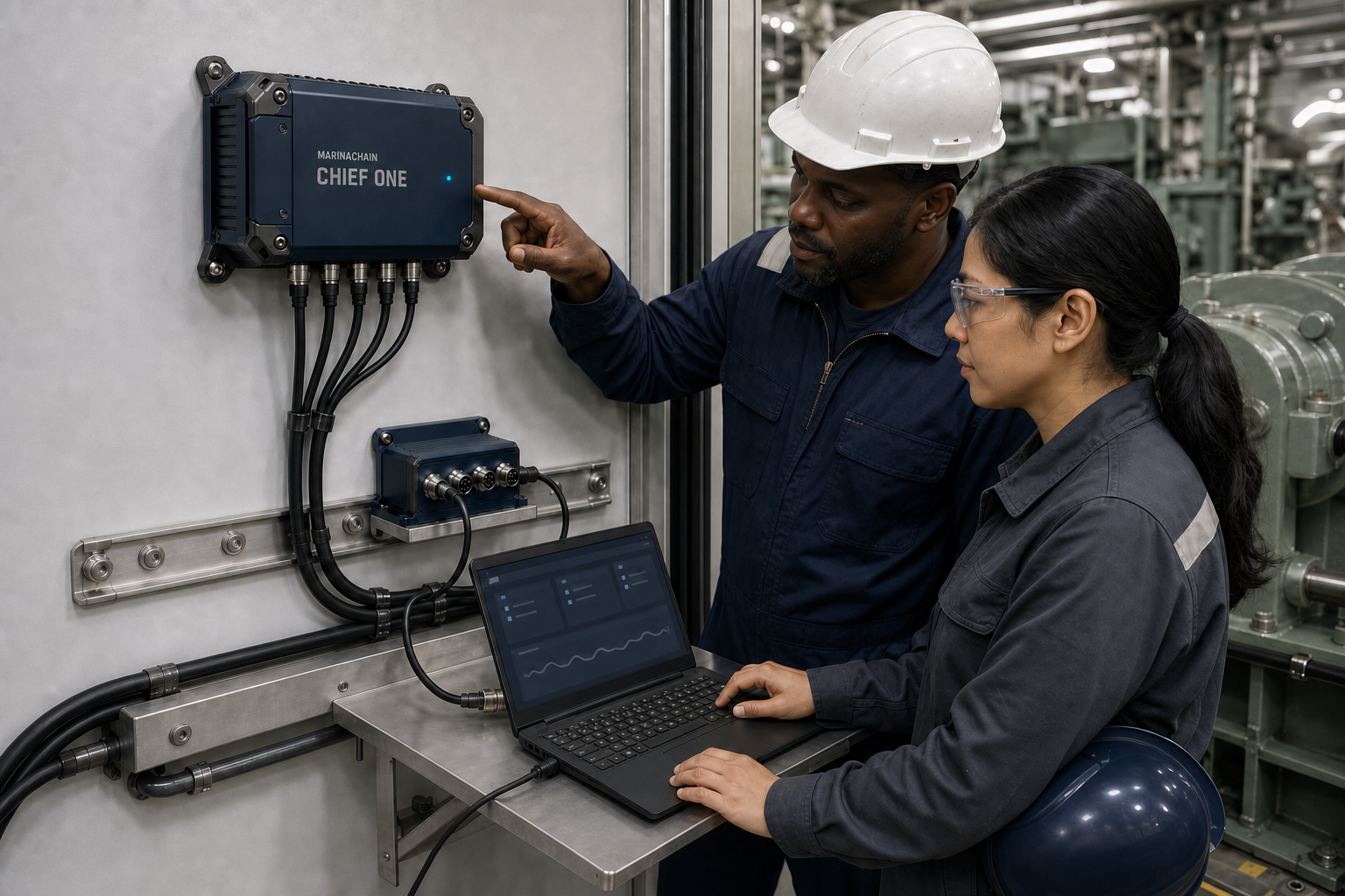
CHIEF ONE is a compact retrofit system designed for selected auxiliary rotating equipment on commercial vessels. Fixed Machinery Pods, a protected Marine Interface and local processing help the crew preserve and review evidence when a machine begins to behave differently.
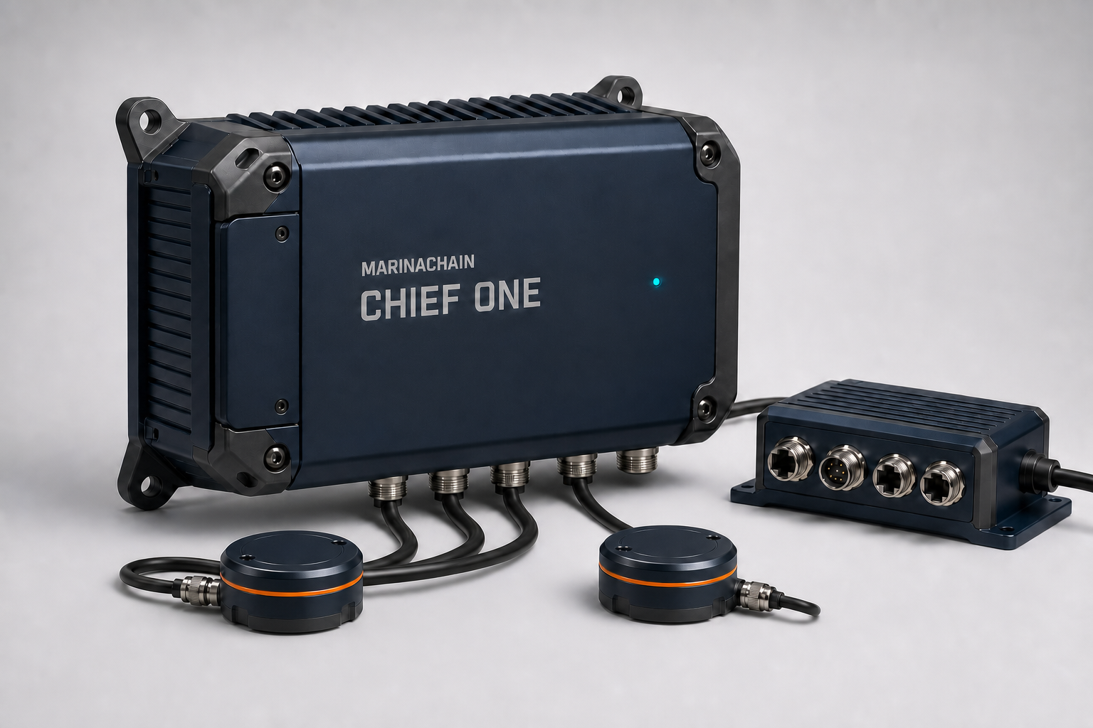
Changes in sound, vibration or temperature can emerge before an existing alarm threshold is reached. Investigation should begin with the signal and its operating context—not a generic score detached from the machine.
CHIEF ONE is being designed to provide read-only condition-monitoring support for selected auxiliary machinery. It does not control machinery or replace OEM or statutory alarms, established procedures, or the judgement of qualified crew.
The proposed architecture separates fixed sensing, vessel operating context and local review, giving each component a clearly defined role.
AT THE MACHINE
Fixed, wired sensing at a selected stationary bearing housing, with a protected cable path and a mounting interface designed for secure, serviceable installation.
VESSEL CONTEXT
Adds configured vessel signals, such as RPM or load, so machinery events can be reviewed in their operating context.
PROTECTED ECR
Designed to process and retain event evidence locally, then support crew review through a separate console interface.
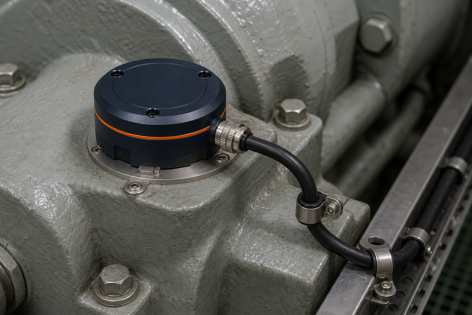
Attachment, anti-rotation, sealing, strain relief and service access all affect whether a signal can be trusted. The production mount and its validation program are therefore treated as core engineering work—not installation afterthoughts.
Machinery Pods, the Marine Interface and the Core are designed to retain each changed signal with its operating context.

Decision support only. CHIEF ONE does not control machinery or replace OEM or statutory alarms.
One evidence trail is designed to carry a machine-specific change through diagnosis, source-cited guidance, repair verification and fleet learning.
MACHINE DNA · ADAPTIVE DEEP LISTEN
Build a vessel-specific Machine DNA, then use Adaptive Deep Listen to combine vibration, contact temperature and configured operating context when behavior changes.
PROBABLE-CAUSE REASONING
Compare the event with the machine reference, RPM or load state and maintenance history to rank probable causes without hiding insufficient evidence.
SOURCE-CITED KNOWLEDGE
Connect the retained evidence to source-cited OEM manual passages and the vessel’s approved maintenance record.
CREW ACTION
Show inspection location, urgency and cited maintenance instructions, then prepare a PMS work-order draft for authorized crew review.
CLOSED-LOOP MAINTENANCE
Compare post-maintenance behavior with the machine reference and preserve whether the intervention restored the approved operating state.
FLEET INTELLIGENCE
Synchronize approved evidence when connectivity allows to support fleet-level learning and analytics without making the vessel cloud-dependent.
This is the intended CHIEF ONE product loop. Each step remains under implementation and validation; measured performance and onboard operation belong to the evidence program.
Wired Machinery Pods capture vibration and contact-temperature signals at selected equipment. The Marine Interface adds configured operating context, while the CHIEF ONE Core processes and retains the evidence locally for crew review.
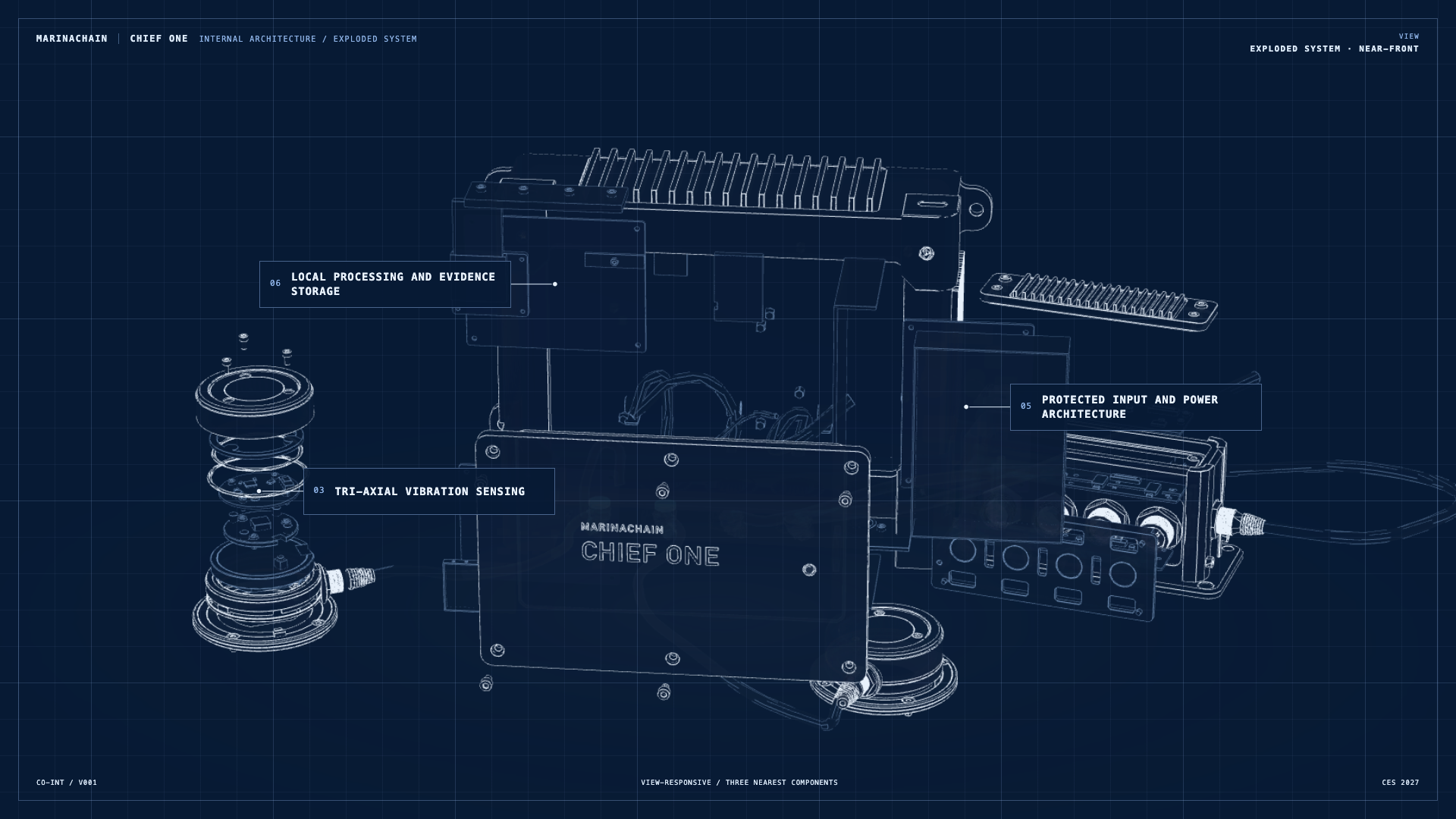
Static labelled viewDrag horizontally, use arrow keys, or press Space to pause.
The human layer matters as much as the enclosure. CHIEF ONE must fit the vessel’s maintenance practice, protected control-room boundary and existing engineering judgement.
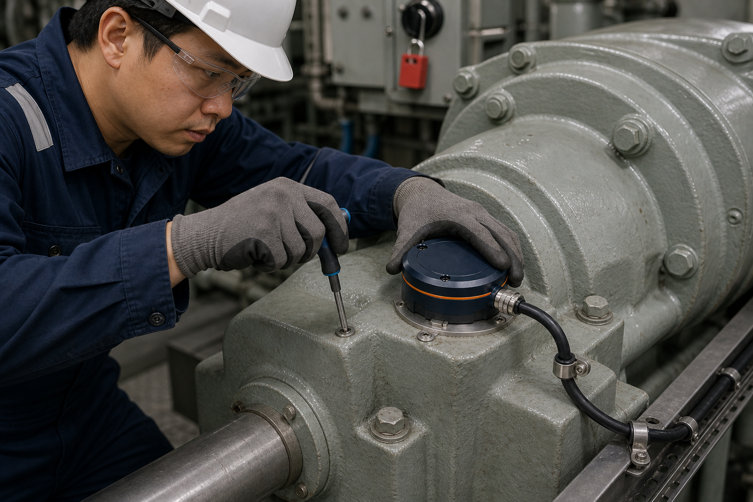
A Pod is mounted on selected stationary machinery, then its cable is restrained and routed toward the protected control-room-side equipment.
The asset, sensor health, implemented context signals and representative operating states are recorded for a machine-specific reference.
A changed signal is paired with its operating context and one specific inspection question, so crew can verify the machine and record their decision.
Follow one machinery-health evidence trail from a subtle change at the machine, through local processing and operating context, to focused review by qualified crew.
Fixed wired sensing, vessel operating context and local evidence give the crew a focused view of what changed and where to inspect.
Capture the change at the machine, preserve its context locally and carry a focused inspection question to the crew.
Product and operational visualization. This film does not represent onboard pilot footage or validated performance.
The evidence program focuses on repeatable results under stated conditions across signal capture, mounting, machinery-space use and onboard operation.
Repeatable signal capture, local processing and a crew-readable event sequence.
Attachment geometry, cable restraint, service access and environmental definition.
A separately scoped vessel trial with agreed equipment, conditions and evidence criteria.
Final configuration, manufacturing plan, support terms and release plan.
CHIEF ONE remains in development. Its launch configuration, pricing, manufacturing route, support terms and general-availability date are not yet confirmed.
Operators can share their vessel type, selected pump or motor, access conditions and operating context for a technical-fit discussion. Any pilot would use separately agreed scope, readiness, responsibilities and evidence criteria.
Request a one-vessel pilotVisit MarinaChain ↗